Introduction to the Di3.630
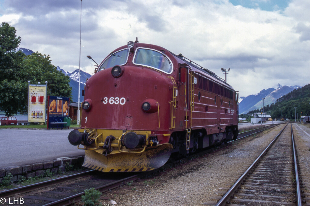
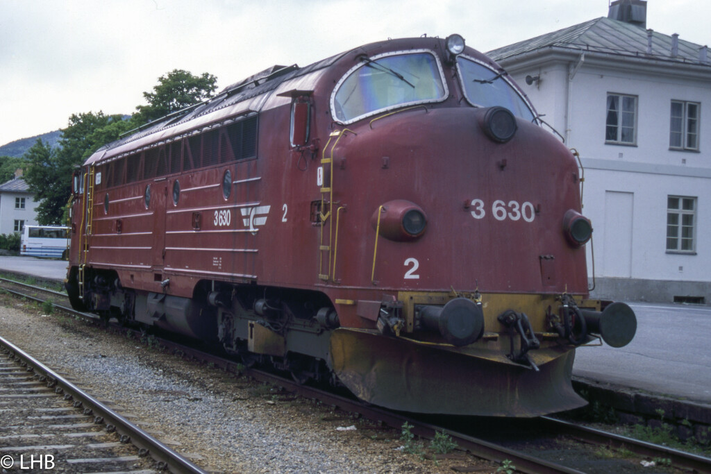
The Di3.630 was part of the very last Di3 series, built in 1969. In 1988 it was the prototype locomotive for the sound isolation that the NSB wanted to do. It had both cabs modified. As the cost was twice as high as forecasted the subsequent locomotives only had cab 1 isolated. This made the 630 a unique locomotive with pansered glass on both sides/cabs.
It was in service for 31 years until 2000, it was sold to a Esposito, a rail maintenance company in Italy. It was in this service until 2006, when it got damaged in an accident. It was put aside and finally scrapped in 2011.
NMJ Superline Di3.630
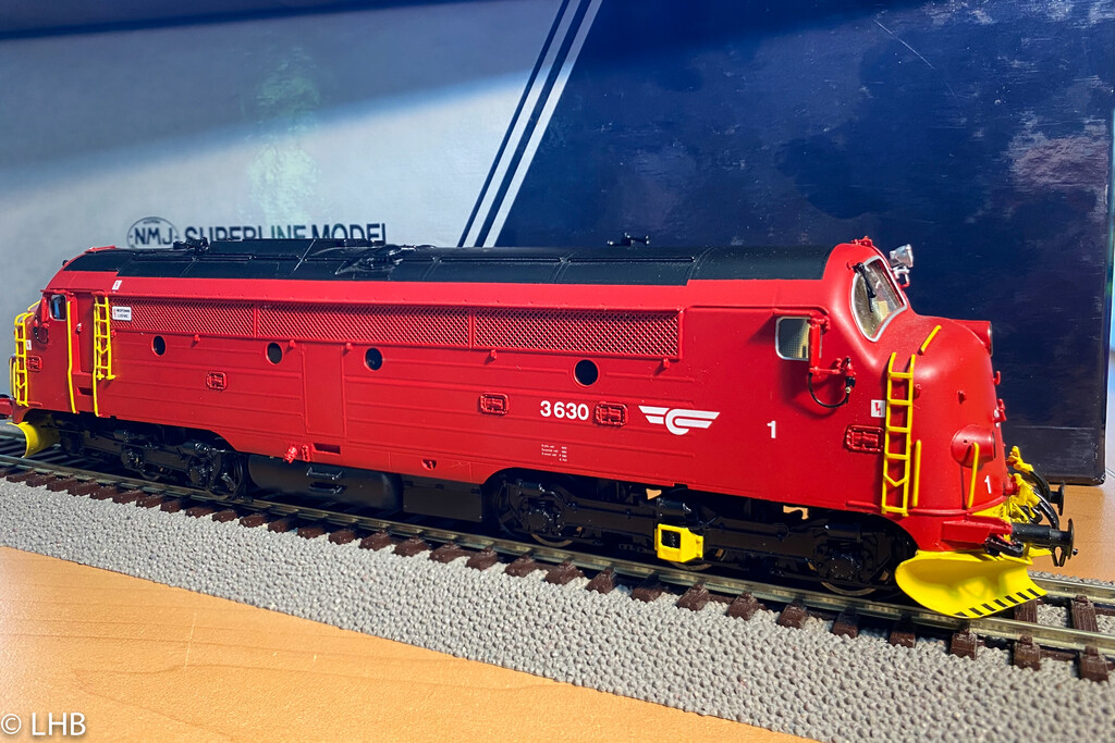
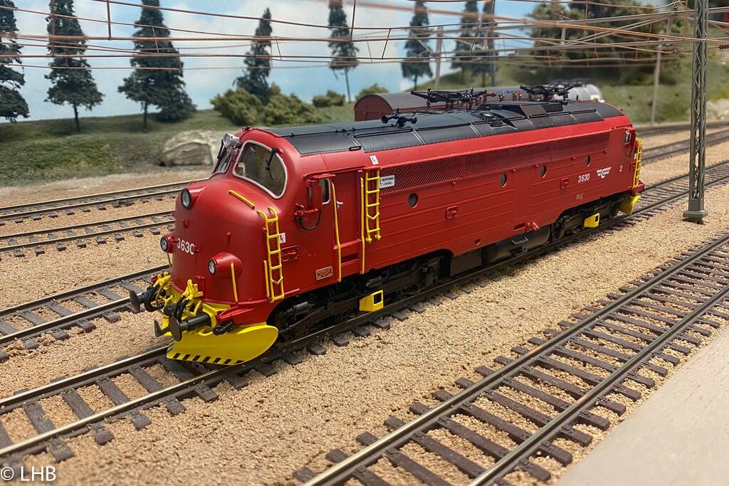
In 1999 NMJ made a serie of highly detailed brass models of the Di3. This is included the Di3.630. At the time this was the only way to get a Di3 model in HO. The Märklin model that was also available wasn't a correct model of a Di3 and really showed it age.
It has a very nice drive and runs great on DC. As it pre-dates DCC, it needs some work to get DCC installed.
DCC upgrade and sound install
In 2003 I installed DCC in the Di3.630. It is described in
NMJ Superline DCC. It has a Lenz LE080XS decoder, which at that time was one of the few decoders that was optimized for coreless motors.
It is time for an upgrade, I wanted to have sound installed and program it to run with all my other Di3 models, which means a setup for use with the ProtoThrottle.
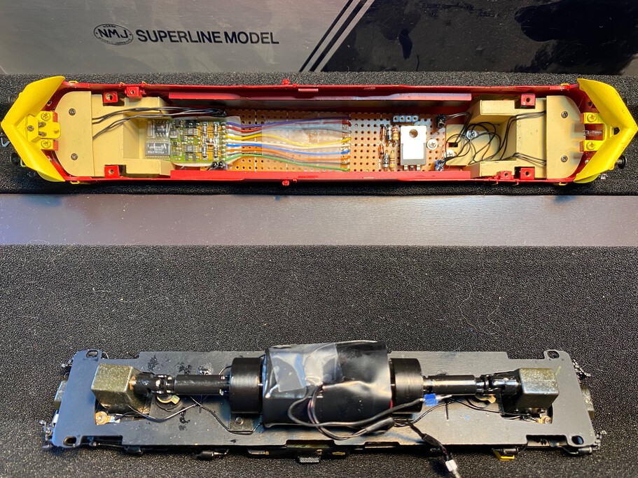
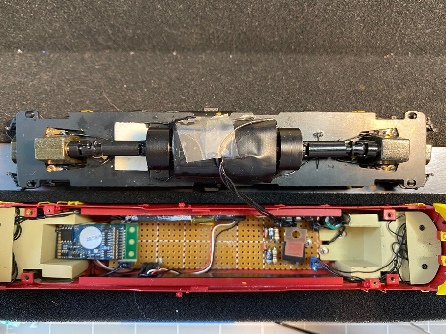
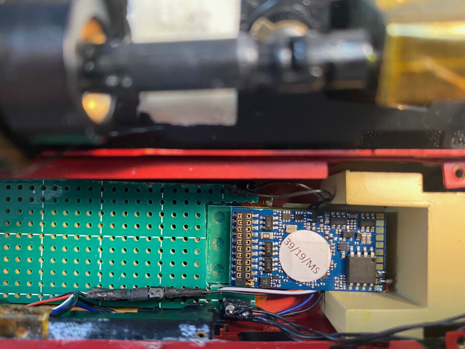
The first picture shows the idea of replacing the Lenz decoder with a MTC21 adapter and a LokSound 5 decoder mounted on that. The speaker would be an iPhone 4S speaker that would fit along one of the sides. The center picture has the board, that I created in 2003, removed and the adapter plate mounted with double sided tape. It also shows the iPhone speaker and a Power Pack. The third picture has some test fitting of the Power Pack and the placement of the speaker and decoder board.
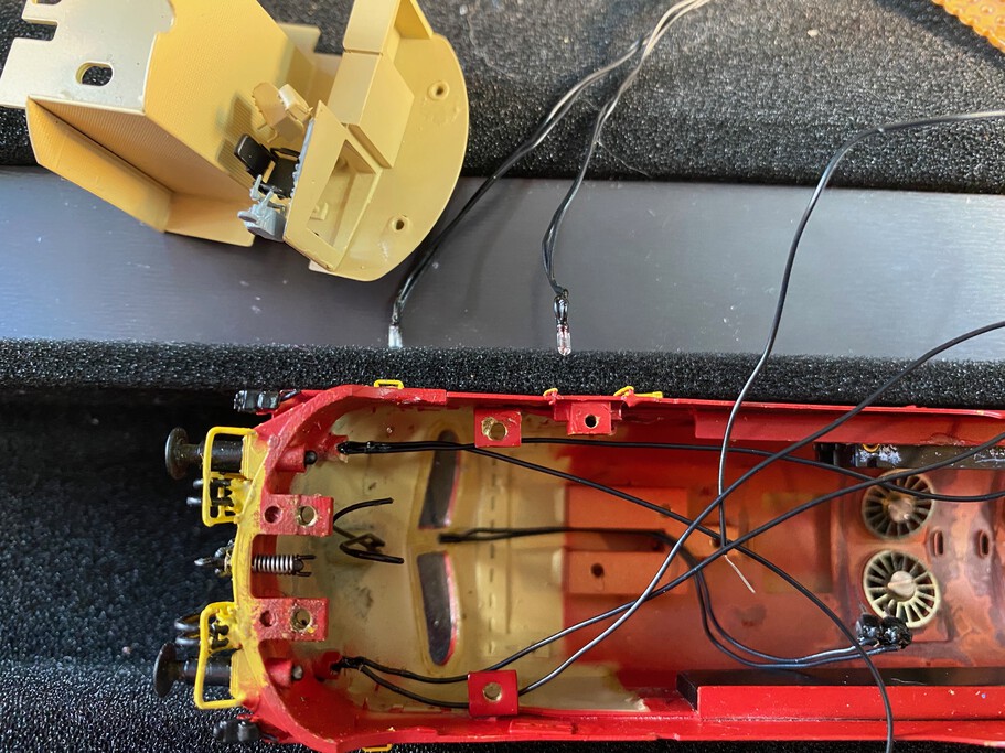
As most brass locomotives of this age, the lights are small 1.5V grain of rice lights. One of the headlights had gone out, so I took the whole interior assembly out to replace the lights. Replacing it would LEDs would be better but that is something for the future.
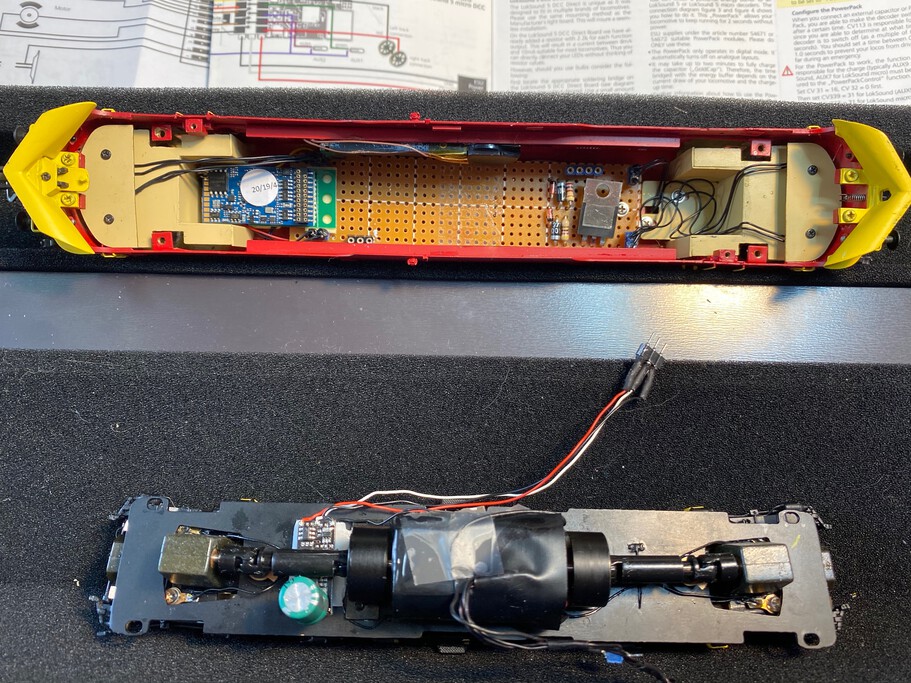
The second picture shows the complete assembly.
While the test drives were successfull, after final aseembly there was a knocking sound from the drive. After taking the shell of again it revealed that there wasn't enough clearance between the top of the MTC21 connector of the decoder and the drive shaft.
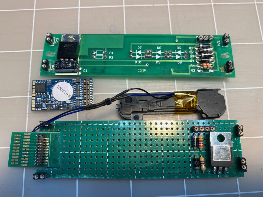
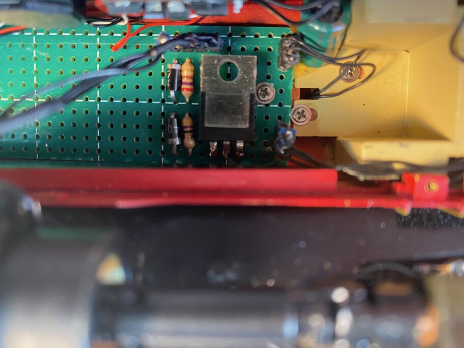
Solution: instead of putting the MTC21 adapter board on top of the PCB board, make it inline!
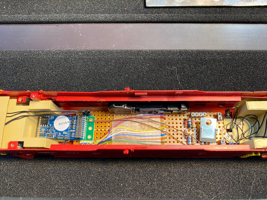
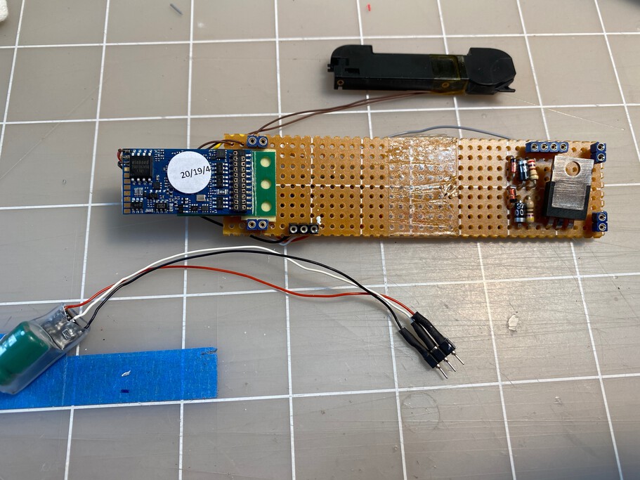
As the board that I created in 2003 was made of brittle PCB board and it failed when I tried to cut a space for the MTC21 adapter board, I had to create a new board. This picture shows the new board (below). The MTC21 adapter board is now inline (at level) with the rest of the board, which means the decoder will stick out a few millimeters less and that is the clearance that is required. The speaker is connected via a small connector, in case it ever has to be replaced. On top is the original NMJ PCB.
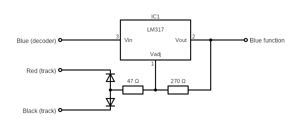
The original NMJ board had a circuit based on the LM317 voltage regulator to create a constant 1.5V for the lights. When I created my own board in 2003 I used the same concept. This schema shows the setup.
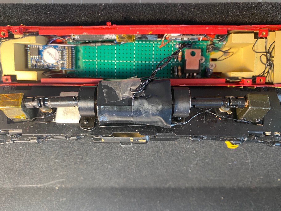
Final assembly of the new board. The Power Pack capacitor is visible just next to the LM317. It has been tucked away in a small gap between the board and the interior wall. The charging board is mounted with tape on the side of the wall, next to the iPhone speaker.
The NMJ Superline Di3.630 is now ready for service on the Dombås layout. I will record a video of the sound in the future and update this page.
Last update: 2020-07-05