Install ESU Loksound decoder in the Piko DSB MY 1147
Introduction to the DSB MY 1147
Piko announced the NOHAB models in 2022. In early 2023 they are now available. For quick summary. The DSB MY locomotives were built by NOHAB between 1954 and 1965. See Danish NOHAB models in HO for more information and also all the other models in my collection.
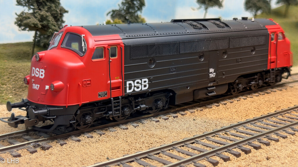
DSB MY 1147 - Odense, Denmark - 1993-07-21
Piko MY 1147
The MY 1147 is part of the last order and was delivered in November 1964. It was the first DSB MY to receive the new design colors in 1972. In 1979 the locomotive got a snow plough installed and also other hand grips etc on the hose. This places the Piko model in the 1972-1979 era. However upon further investigation of old photos, the ITC connector (the white connector on the front of the Piko model) was replaced by a receptable under a small flap/door in 1975. This places the locomotive in the 1972-1975 era.
This is of interest, as the front light signals were very different before and after 1975. Before 1975 only the top light was used, after 1975 all three lights (A signal) were used.
I ordered an analog/DC locomotive and this page will show how to install a decoder into the locomotive. The Piko model has a PLUX22 socket, therefore a decoder installation is very straight forward.
In analog mode only the top light is lid, clearly using the correct front light signals.
DCC Sound Installation
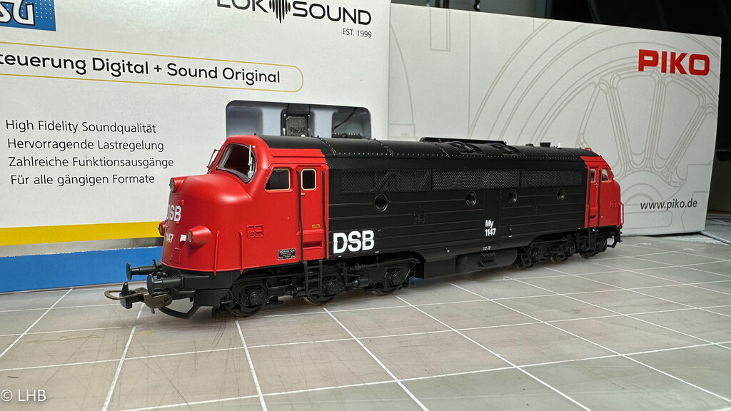
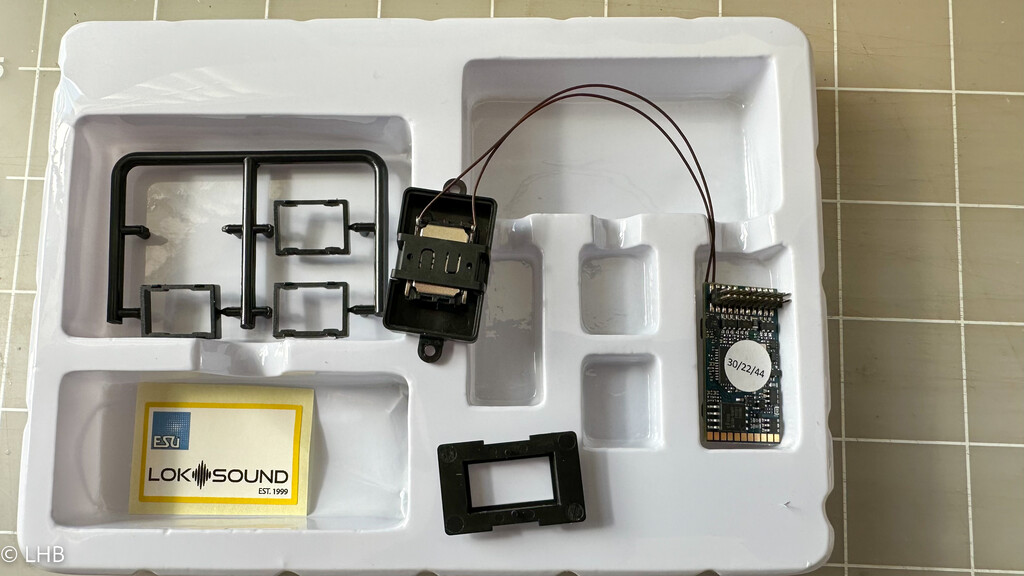
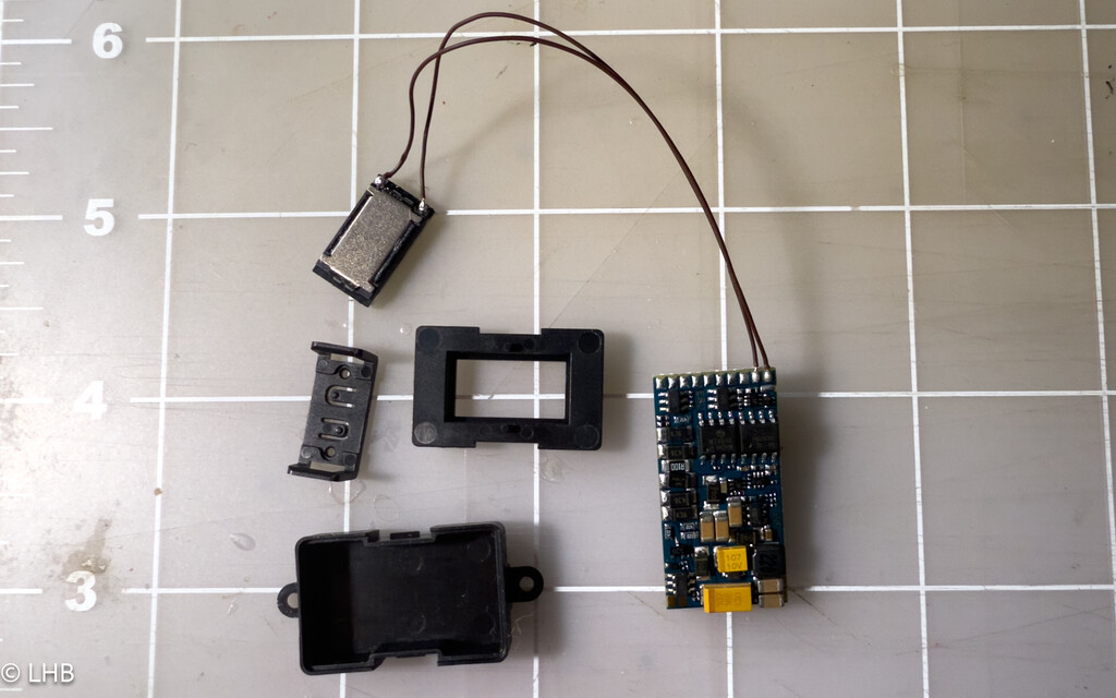
The parts for this story. The Piko MY, catalog no: 52483 and an ESU Loksound 5 decoder (58412).
The decoder will get the sound of ESU project 96452, which is an ESU NOHAB project. I will adjust the function mapping to be closer to my standard (for Proto Throttle control).
I was approached by a former DSB engineer about the ESU project (96452). This made me revisit this installation, therefore please also read the DCC Sound Installation Revisited section.
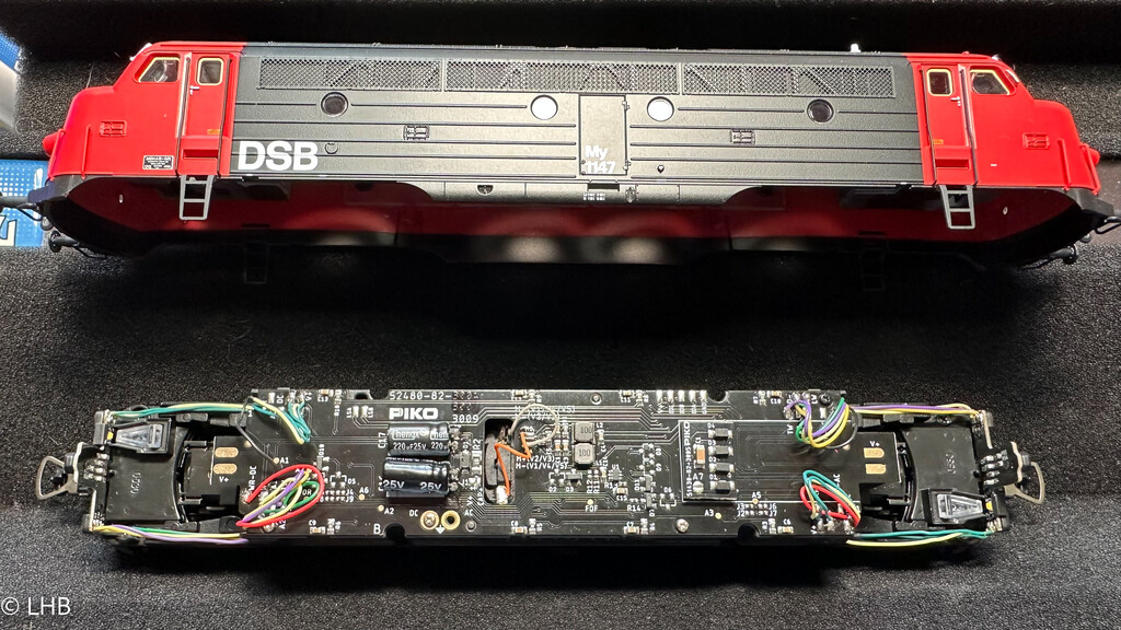
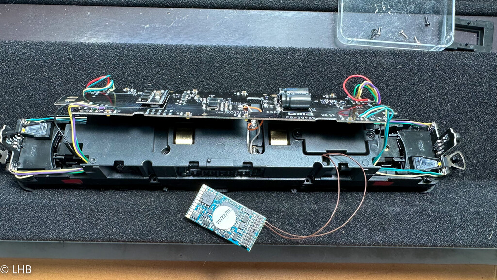
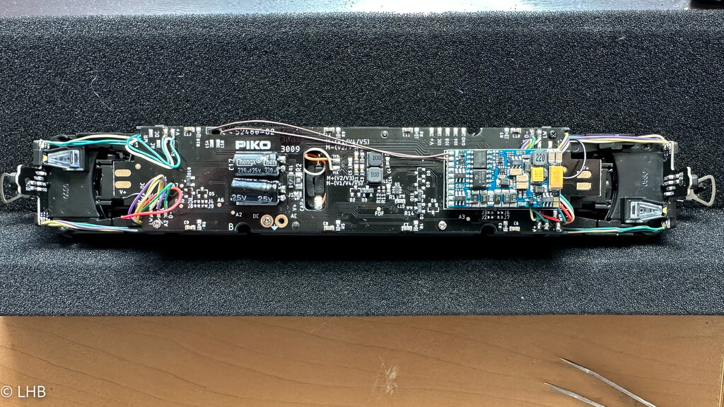
The shell can be removed by removing four screws. This shows the PCB from the top. The PLUX22 dummy connector is cleary visible to the right. This will be removed and replaced by the decoder.
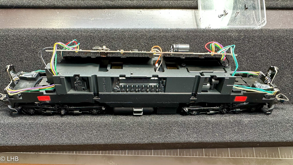
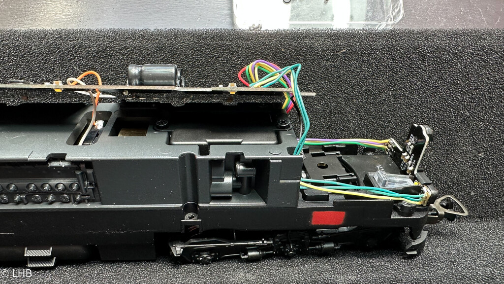
The locomotive is prepared for housing a speaker. To get to this, the PCB needs to be lifted up. A few screws will do the trick. Clearly visible is the speaker box, which is held in the frame by two additional screws. They are being removed and the speaker box/housing is lifted out.
The speaker housing/box is sized for a 16x9 sugar cube speaker. The ESU is standard delivered with a 15x11 speaker. I've ordered a 16x9 speaker (Digikeys CMS-16093-078SP). In the meantime I will lock the 15x11 speaker under the housing clip. To have it fit, I will use the bottom plate of the ESU speaker box, this is why you see this being removed from the sprue in the right photo.
The speaker box is placed back in position and screwed in. Then the PCB is put back in position. That leaves the ESU Loksound 5 decoder to be plugged into the PLUX22 socket and we are ready.
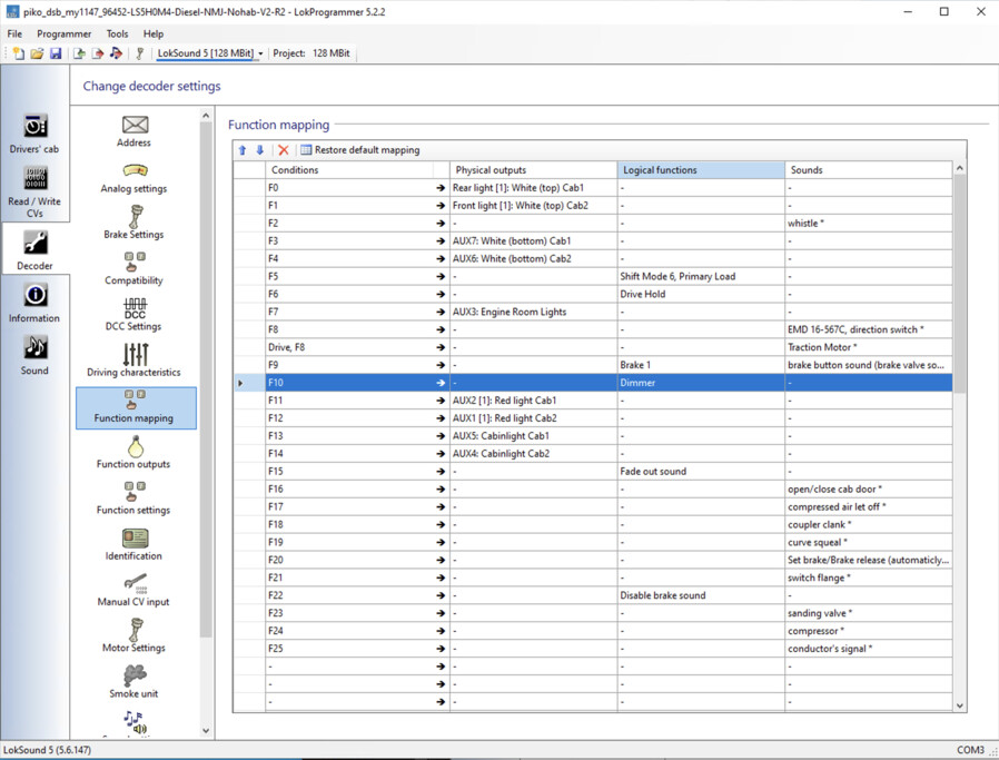
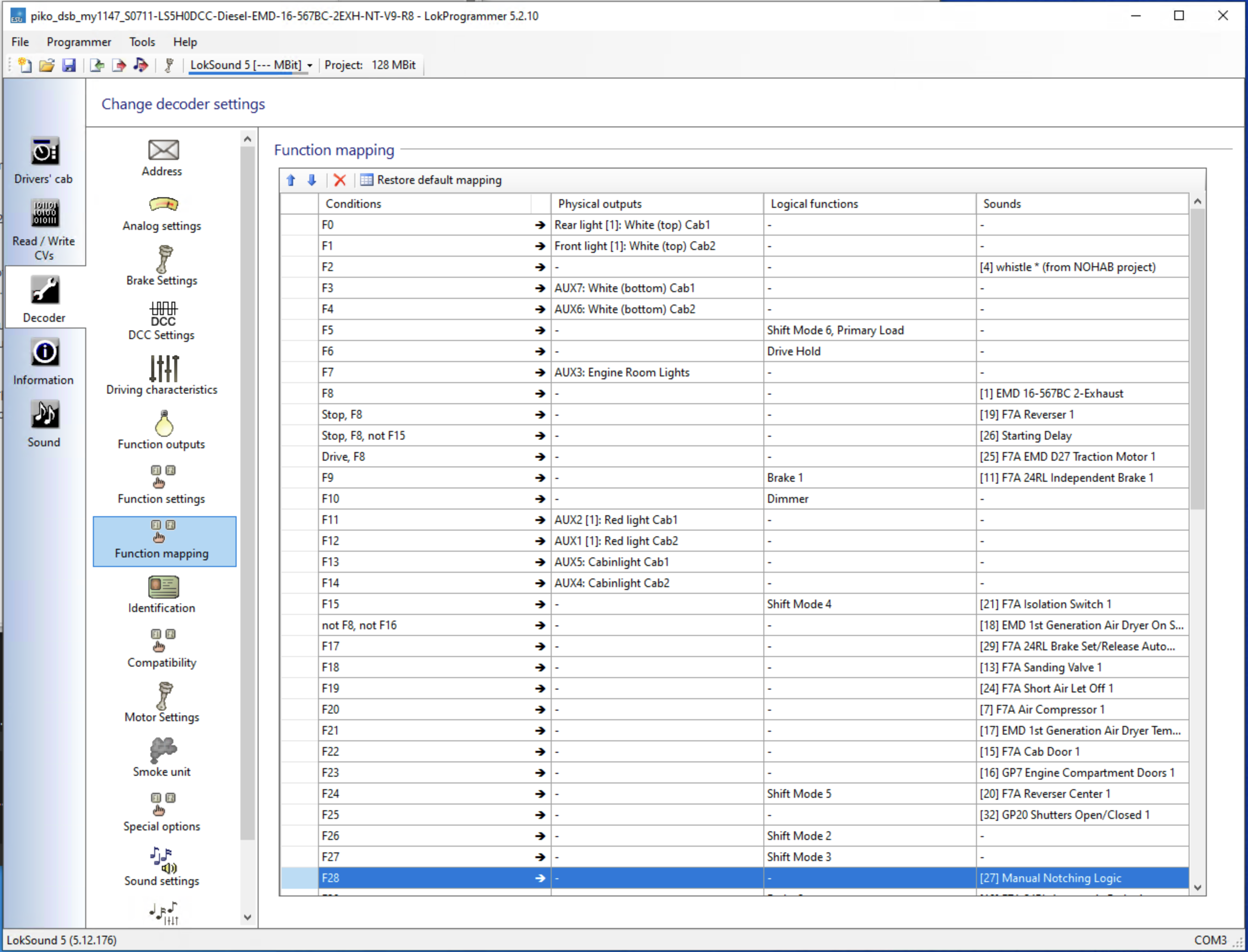
Next is the function mapping. The instruction manual shows the light assignment and this is the basis of the function mapping. In this case I'm not using directional lights, each light is separately controlled by a function key.
The original ESU project 96452 doesn't have the Drive Hold feature and I feel this is a very important feature. It allows to control the engine notches (RPMs) separate from the speed. This is one of the reasons why I use ESU as my standard choice of decoders.
DCC Sound Installation Revisited
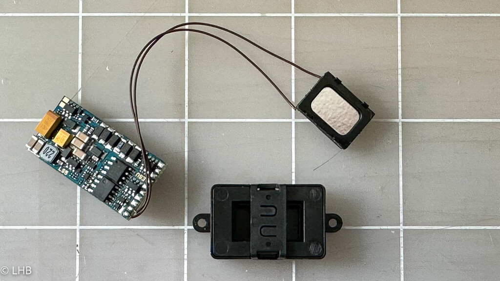
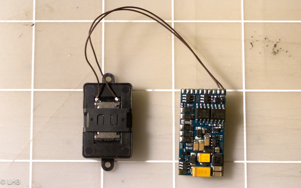
As described earlier the speaker housing is sized for a 16x9 speaker. In the meantime I bought a 16x9 speaker (Digikeys CMS-16093-078SP). These two photos show the new speaker and how it fits into the speaker box/housing.
I was contacted by Thomas Albøg Olsen, a former DSB engineer. He shared that there are two issues with the sound project that I used. The first issue is that the later DSB MY locomotives had a different exhaust stack than the earlier models. This gives the later models (this includes the 1147) a different sound. Based on his analysis the ESU S0711 project comes close to that sound. The second issue is about notch 1. On the Danish GM locomotives in notch 1 the generator was magnetized but the engine was still in idle. Only with notch 2 the RPMs were increased. The ESU S0711 project supports this as well.
The new sound project just starts out with the latest S0711 version (which is an EMD 16-567BC with 2 exthausts). I added the whistle from the original project and then changed the function mapping for F0-F14 according to my standard Proto Throttle based mapping.
A demo that shows both the old project and the new project.