Introduction to the Piko 216 033-1
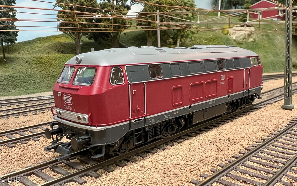
Piko introduced a model of the 216 010-9 in 2020. A serie model of the 216 was released in 2021 with the 216 177-6 in the ocean blue-beige color scheme. In 2022 the old red color followed and this page covers this model.
See class 216 models in HO for a brief history of the class 216 and all the 216 models in my collection.
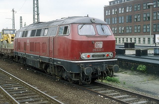
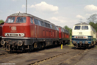
Specifically to the 216 033-1. It was built in 1965 and was in the older red color until 1984. In October 1984 it had a revision and got the ocean blue-beige color. It was in service until May 1987 when it was retired and scrapped in July 1987.
The Piko model has the revision data of the U2.0 revsion in January 1977. It has the depot of Gelsenkirken-Bismark, which puts the model in the era from January 25, 1977 until December 31, 1981.
The Piko model has the revision data of the U2.0 revsion in January 1977. It has the depot of Gelsenkirken-Bismark, which puts the model in the era from January 25, 1977 until December 31, 1981.
DCC Sound Installation
The parts for this story. The Piko 216, catalog no: 52415. An ESU Loksound 5 decoder (58412) and an ESU speaker (50330).
The decoder will get the sound of ESU project 22442 and the function mapping of the ESU Piko project 94473.
The shell can be removed by removing two screws. This photo shows the shell (top), the two screws and the rest of the locomotive. The pcb has a PLUX22 connector and the decoder is placed underneath the pcb in the opening that is visible under the PLUX connector.
To get to the speaker enclosure the pcb screws are removed and the pcb can be moved a little bit Then two very small screws become visible and the speaker enclosure can be removed.
In the photo the pcb is slightly moved and the small screw hole of the speaker enclosure is visible.
The ESU speaker comes with an enclosure (the white box on the left). The speaker leads are soldered to the speaker and then the speaker is mounted into the built-in speaker enclosure.
The first photo shows the mounted decoder and the speaker enclosure is put back. The brown speaker wires are not connected yet. The second photo shows the pcb screwed back in and the speaker wires are soldered to the pcb (lsa and lsb positions).


