Overview of the Fleischmann 03 1001 model
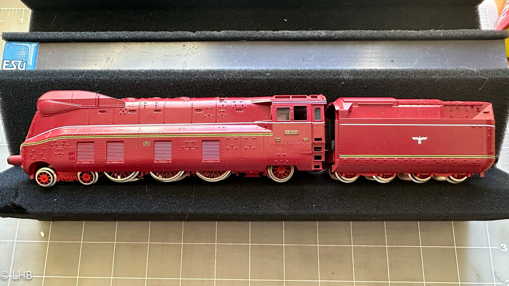
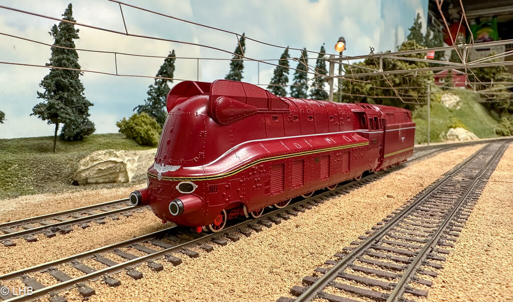
The 03.10 was an express train steam locomotive. Initially they were in full streamline plating, like the Fleischmann model.
This particular model is Fleischman 4173 in the full streamline version as it was in the 1940's. The 03 1001 was built in 1939. The streamline plating was removed in 1950 and was in service until 1966.
The Fleischmann model is from 1985 and pre-dates DCC.
DCC Install
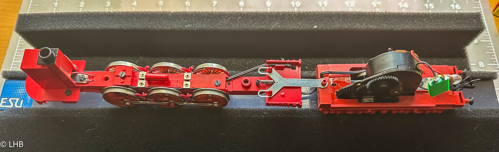
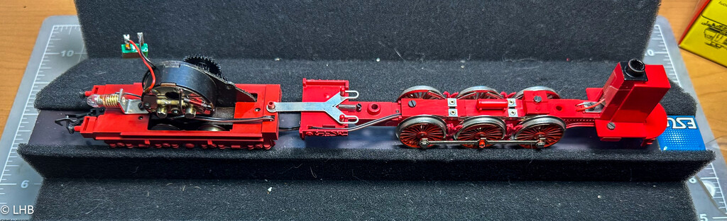
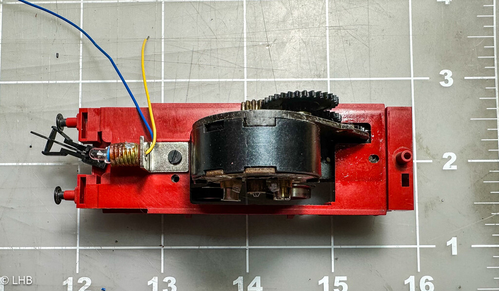
After removing the body shell from both the locomotive (removal of some screws) and tender, the technical layout of the model is visible. The standard Fleischmann round motor is in the tender. The main power pick up is in the locomotive and two wires run from the locomotive to the tender.
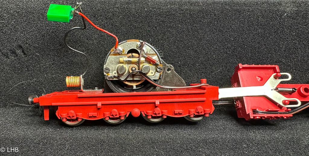
Detailed view of the standard round motor in the tender. The green electronic item is a diode for the tender light. The motor shield is not fully electrically isolated from the frame and that is where we start with the DCC conversion.
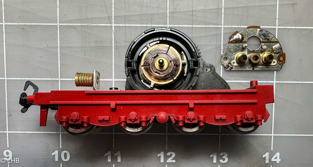
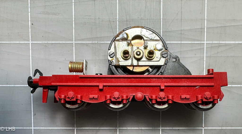
The motor shield is removed from the motor. You can now see the collector and the fact that this model has had some running time already. The next photo shows the shield placed back but now the shield is fully isolated. With a dremel tool the motor brush connection on the left is fully isolated from the rest of the shield.
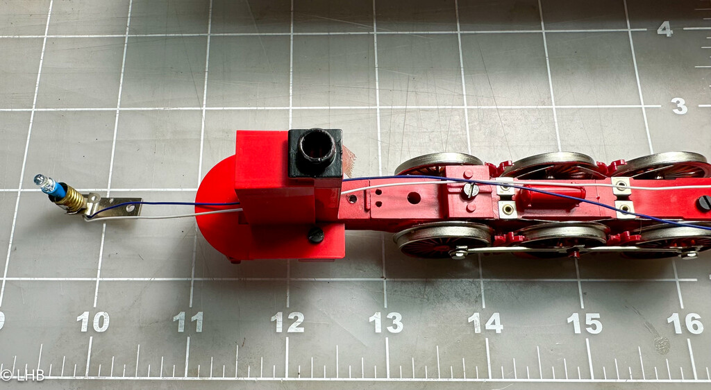
The front light assembly is removed and an LED is placed in the light socket. It is completely electrically isolated using shrink wrap. The white and blue wire will go to the decoder. A resistor will be needed as well.
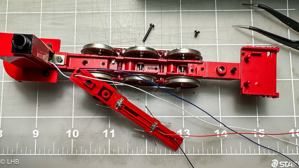
The power pick wires (red and black) are connected to the wipers and we can use the space to guide the wires. The four wires will be going to the tender, as the decoder will be placed in the tender.
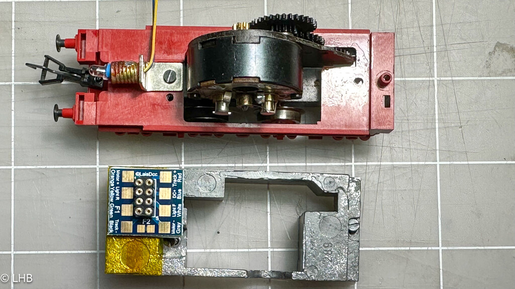
The light in the tender will be replaced by an LED as well. After some proof fitting it was clear that an 8-pin socket can fit in tender and it is placed on the weight around the motor. Some tape is used to electrically isolate the socket board from the weight.
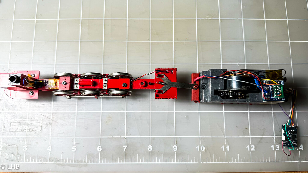
The wires from the locomotive are in 1/16" red shrink tube. This makes for a nice single wire connection between the locomotive and the tender. Also visible in the photos are the resistors for the LEDs. The rear LED resistor is hiding in blue shrink wrap. The front resistor is tied to the smoke stack.
The locomotive is ready for a test drive.